
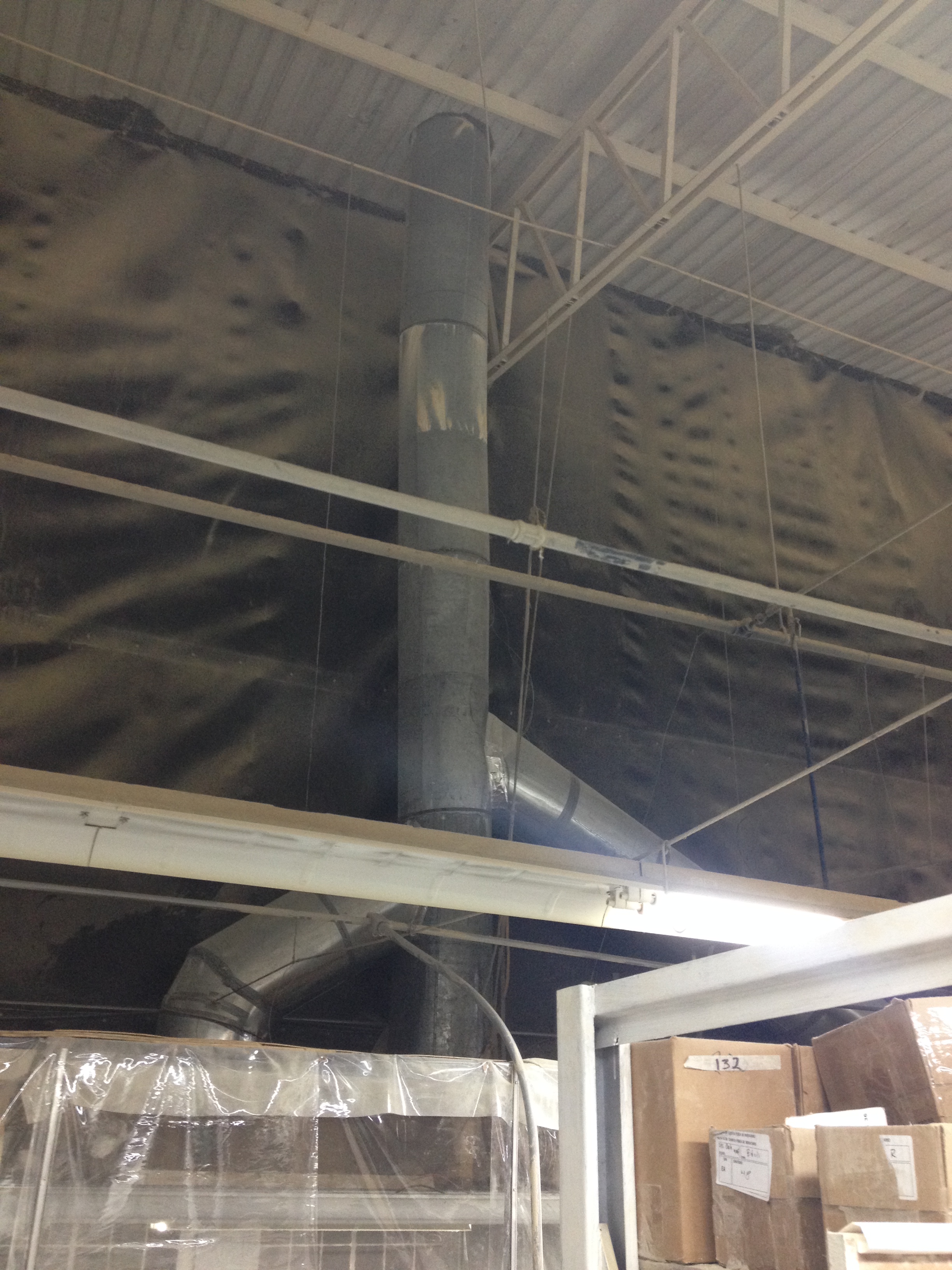
In this photo, an installer has chosen to manifold three spray booth exhaust duct runs. (A manifold is a pipe or chamber branching into several openings.)
This layout probably looked great on paper and reduced the number of roof penetrations from three to just one.
Reality is such as nasty teacher. The static pressure (resistance to the flow of air) was greater in the top portion of the ductwork than in the spray booths. The ductwork downstream from the manifold point (above the joints) should be much larger than what is in the photo. The air ventilated out of one booth actually flows into its neighbor.
Our booths are designed to meet specific airflow needs and we design them with ductwork. The spray booths in the photo were designed to have individual exhaust ductwork runs; they were not installed according to the design or instructions provided by Standard Tools.
Manifolding of exhaust ductwork is allowed by NFPA-33 only if devices exist in the ductwork that detect improper airflow. The static pressure within the spray booth will change as the overspray builds up in the exhaust filters and as the obstruction within the booth changes (based on size and shape of parts in the spray booth). This can be very technical and overly-complex. The simple rule, and what Standard Tools recommends, is no manifolding of exhaust ductwork. Keeping ductwork simple is the least expensive and best performing strategy in the long run. We suggest that you install your booth, and your ductwork, according to our recommendations to ensure proper airflow within your booth.